Data Flow Diagram Symbols and Rules
Using any conventions DFD rules or guidelines the symbols depict the four. What is data flow diagram.

Data Flow Diagram Symbols Lucidchart
The object orientation of a system is indicated by a class diagram.

. Rules and symbols are available from standardization organizations. A data flow diagram DFD maps out the flow of information for any process or system. A PFD represents the process flow as it physically exists when walking the process A PFD helps with the brainstorming and.
In software and systems engineering the phrase use case is a polyseme with two senses. How to draw DFD online. Flowchart Symbols Components.
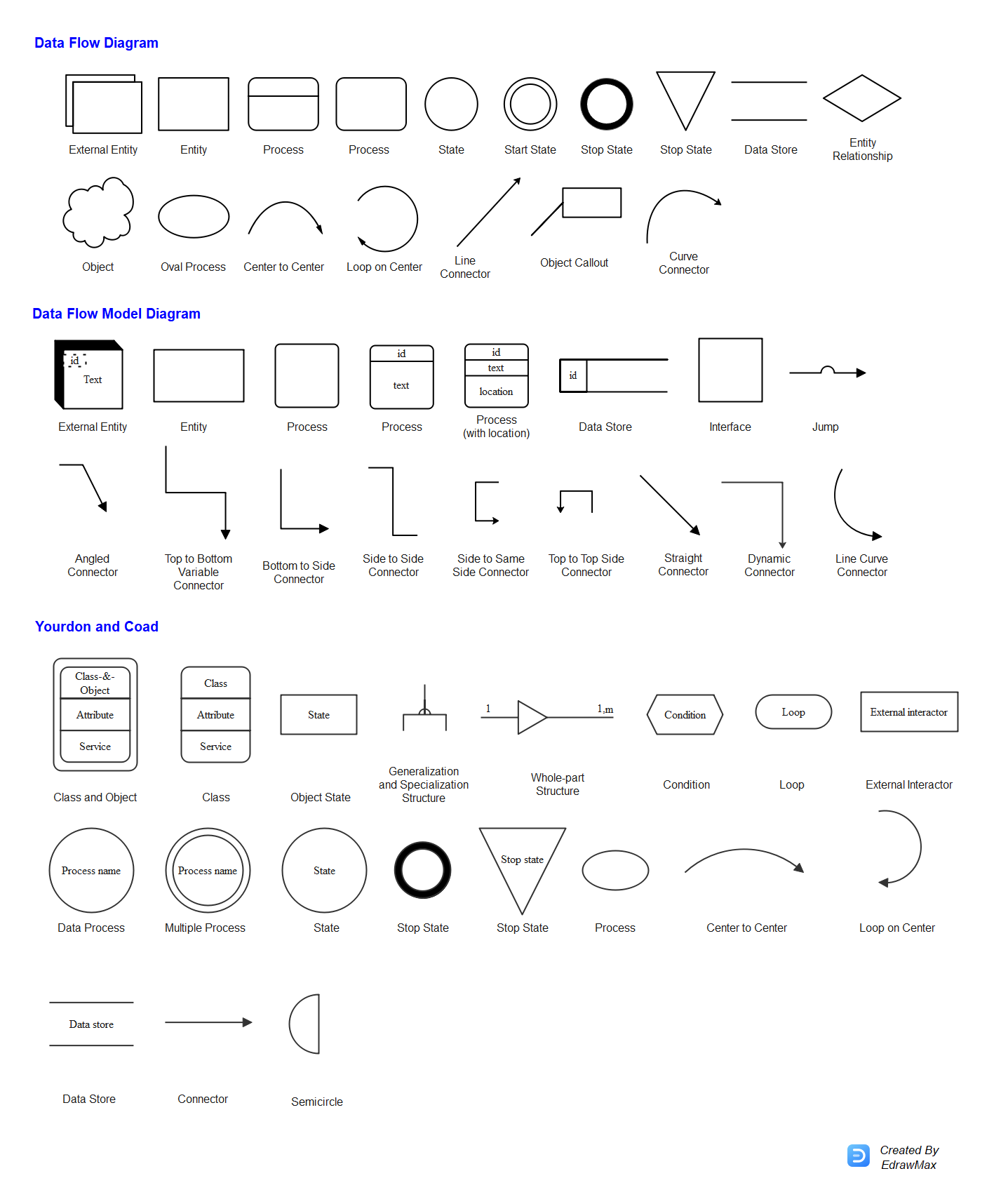
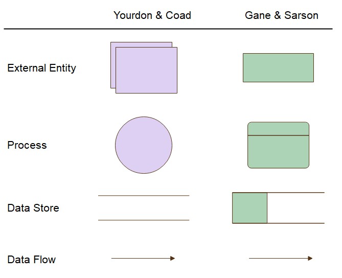
Our DFD shape libraries contain standard symbols for both Gane-Sarson and Yourdon-Coad methodologies allowing you to create clear and consistent data flow diagrams online in minutes. An example data-flow diagram As can be seen the DFD notation consists of only four main. The process flow diagram below is an example of a schematic or block flow diagram and depicts the various unit processes within a.
Physical DFD focuses on how things happen by specifying the files software hardware and people involved in an information flow. UML Class Diagrams is a type of static structure diagram that is used for general conceptual modeling of the systematics of the application. It uses defined symbols like rectangles circles and arrows plus short text labels to show data inputs outputs storage points and the routes between each destination.
Such a diagram would illustrate the object-oriented view of a system. Rules and symbols for creating DFD. DFD describes the processes that are involved in a system to transfer data from the input to the file storage and reports generation.
Once data is sufficient move on to diagram software. Furthermore extra features may help point out incomplete sections in the diagram. Look at the diagram to get a feel for the symbols and notation of a data-flow diagram.
Best software tools and solutions. The differences and symbol rules are divergent enough to make it difficult for technologists to read the DFDs of methodologies theyre not familiar with. Multiple online tools smoothen the drawing process and generate professional-looking graphic charts.
Data flow diagram DFD is the part of the SSADM method Structured Systems Analysis and Design Methodology intended for analysis and information systems projection. A data flow diagram DFD is a graphical or visual representation using a standardized set of symbols and notations to describe a businesss operations through data movement. Data flow diagrams are used to graphically represent the flow of data in a business information system.
Bijan Elahi in Safety Risk Management for Medical Devices Second Edition 2022. Keep the symbols consistent to avoid misunderstanding. Data flow diagrams are intended for graphical representation of data flows in the information system and for analysis of data processing during the structural projection.
These same rules and constructs apply to all data-flow diagrams ie for each of the different software process activities in which DFDs can be used. Context data flow diagram example in PDF with an explanation step by step. Often used in the plural to suggest situations where a piece of software may be useful.
Level 1 data flow model diagram example in PDF with an explanation. In fact a simple flowchart constructed with just rectangular blocks and flowlines can already get most jobs done. Before you embark on creating a data flow diagram it is important to determine what suits your needs between a physical and a logical DFD.
Definition advantages and disadvantages a tutorial for beginner. Or flow chart software using a library of chemical engineering symbols. Gane-Sarson notation was introduced in Chris Gane and Trish Sarsons 1977 book Structured Systems Analysis.
Operational data temperature pressure mass flow rate. Logical DFD focuses on the transmitted information entities receiving the information the. A potential scenario in which a system receives an external request such as user input and responds to it.
Flowchart is a very intuitive method to describe processes. A usage scenario for a piece of software. A data flow diagram tool allows you to take any flow of information for a process or system and condense it into a coherent.
Add specific rules within the. Data flow diagram often used. When it comes to system construction a class diagram is the most widely used diagram.
As such in most cases you dont need to worry too much about the standards and rules of all the flow chart symbols. Process Flow Diagrams PFD are a graphical way of describing a process its constituent tasks and their sequence. 14713 Process Flow Diagram.
Data Flows Common Dfd Mistakes
Data Flow Diagram Dfd Symbols Edrawmax
Data Flow Diagram Dfd Symbols Edrawmax

Flowchart Symbols Meaning Complete Guide 2022
0 Response to "Data Flow Diagram Symbols and Rules"
Post a Comment